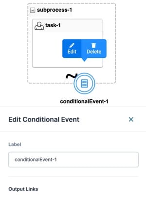
The Conditional Event node uses logic to redirect a workflow that's currently in a Sub-Process node. The conditional logic specified in the Conditional Event node's outgoing link checks for data collected in the Sub-Process node. If the data matches the logic check's parameters, it directs the workflow out of the Sub-Process node and to the linked node.
The Conditional Event node checks logic at these points in a Sub-Process workflow:
Beginning of the Sub-Process.
End of each task in the Sub-Process.
End of the Sub-Process.
Each Sub-Process node can only contain one Conditional Event node. The Conditional Event node includes one output port that links to a single node outside of the Sub-Process node. The Conditional Event node's Output link contains the logic used to trigger the node.
Similar Logic Nodes
While the following nodes have similar functions, the Conditional Event node is different from Gateway nodes in the following ways:
Conditional Event node: Uses conditional logic to redirect a workflow from a Sub-Process node to another path.
Exclusive Gateway node: Uses conditional logic to redirect a workflow to one or more paths outside a Sub-Process node.
Inclusive Gateway node: Uses conditional logic to redirect a workflow to one or more paths outside a Sub-Process node.
Settings Menu Description
Let's explore the node's Settings Menu. This menu displays as a blue menu bar, either above or below the node, when you select the node itself. This node has these Settings Menu options:
Setting | Description |
|---|---|
Edit | Opens the Edit Conditional Event window, where you can configure related settings. |
Delete | Removes the Conditional Event node from the Sub-Process. |
Edit Conditional Event Window Description
Click the Edit button to display the Edit Conditional Event window.

Setting | Description |
|---|---|
Label | The name of your node. By default, the Label displays as Define your labels by associating them with the role of the node. |
Output Links | Displays the logic and linked node for each path from the Conditional Event node. You can edit each item from here. |
X (Close) | Closes the Edit Conditional Event window. |
Conditional Event Links Settings Menu
Selecting the Conditional Event link opens a Settings Menu. This menu displays as a blue menu bar above the link indicator. The menu has the following options:
Setting | Description |
|---|---|
Edit | Opens the Edit Conditional Event Link window. From there, you can configure settings relating to the Conditional Event link. |
Delete | Removes the link from the workflow. |
Edit Conditional Event Link Window Description
Clicking the Edit button displays the Edit Conditional Event Link window.
Setting | Description |
|---|---|
Label | The name applied to the link. This label is optional and displays below the link once set. Labels should be user-friendly and well-associated with the role of the node. |
Status | You can enter a text value here. Other components can query the Status value of a link. When the workflow passes the link, the Status value populates with the Status field text. |
Logic | Sets the logic for the Conditional Event node link. The Conditional Event link icon changes from The expression typically consists of a Property ID, an operator, and criteria (value) for matching. For example:
The Logic field also supports Excel formulas, like the following:
The Property ID should reference a field accessible to your workflow. For example, a field present in the workflow submission. The Logic field autopopulates Property ID values as you enter text.
Logic expressions support the following operators: |
Default | This setting makes this link the Default link. If no other links evaluate as true, the workflow follows the Default link. You can only have a single Default link per Conditional Event node. When the Default setting is set to The Default setting is set to |
Unidirectional | Sets the link one-way. End-users cannot navigate back through a unidirectional link. The link has a double arrowhead when the Unidirectional setting is set to The link has a single arrowhead when the Unidirectional setting is set to By default, the Unidirectional setting is set to |
Use Flash Message | When set to ON, you can create a flash message for this link. Flash Messages are alerts that display at the top of the workflow in Express View. They show when an end-user navigates past a link that has a Flash Message enabled. By default, the Use Flash Message setting is |
Adding a Conditional Event Node
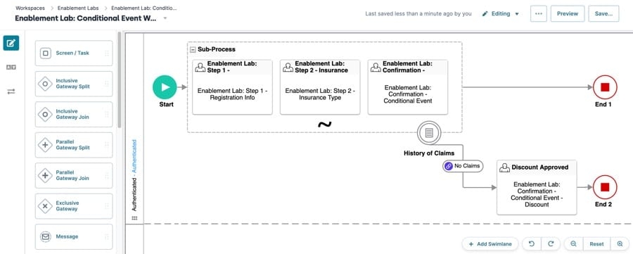
For this example, set up a workflow that verifies an insurance applicant’s eligibility to receive a discount. Use a Conditional Event node to determine if the applicant meets the minimum requirements to qualify for the discount.
If the Conditional Event node's logic statement evaluates as true, the workflow follows the link to an external node. If the logic is false, the workflow proceeds to the next Sub-Process task. If there are no further Sub-Process tasks, the Sub-Process is complete, and the flow ends.
Conditional Event logic evaluation only happens on Sub-Process forward navigation.
This configuration assumes you've created a workflow and have access to modules in the training environment.
Configure the Sub-Process and Task Nodes
First, add the Sub-Process node and accompanying Task nodes to the Authenticated swimlane. You can connect the Task nodes to your own modules, or use the Enablement Lab modules in the following instructions.
In the Workflow Builder, drag and drop a Sub-Process node into the Authenticated swimlane.
Drag and drop three Task nodes inside the Sub-Process node.
Select a Task node and click Edit.
In the Label field, enter
Step 1.From the Module drop-down, enter or select
Enablement Lab: Step 1 - Registration Info Conditional Event.Click X (Close).
Repeat this process for the other Task nodes using the following information:
Label
Module
Step 2
Enablement Lab: Step 2 - Insurance Type Conditional Event
Discount Eligibility
Enablement Lab: Confirmation - Conditional Event
Click X (Close).
Connect the output port (right) of the Start node to the input port (left) of the Sub-Process node.
Configure the First End Node
This first End node marks the end of your workflow if the Conditional Event logic is false.
Drag and drop an End node into the Authenticated swimlane.
Click Edit.
In the Label field, enter
End 1.Click X (Close).
Connect the output port (right) of the Sub-Process node to the input port (left) of the End node.
Configure the Conditional Event Node
Now you're ready to set up the Conditional Event and associated logic.
Drag and drop a Conditional Event node onto the Sub-Process node.
Click Edit.
In the Label field, enter
History of Claims.Click X (Close).
Configure the Fourth Task Node
Next, set up the fourth Task node. Your workflow proceeds to this node if the Conditional Event logic is true. If your applicant has not made any claims in the past three years, they see the discount approval message in the linked module.
Drag and drop a Task node into the Authenticated swimlane.
Click Edit.
In the Label field, enter
Discount Approved.From the Module drop-down, enter or select
Enablement Lab: Confirmation - Conditional Event - Discount.Click X (Close).
Configure the Conditional Event Link
Next, configure the Conditional Event Link to set up the logic that determines whether to display the discount approval message.
The claimsHistory Property ID represents a Radio Buttons component question in the Step 2 module. The question asks your applicant if they have made any claims in the past three years. The claimsNo value is stored in the submission data when your applicant answers No.
If your applicant answers No in the Step 2 module, they proceed to the Discount Approved Task node. There, they see a discount approval message. If they answer Yes, they proceed to the Discount Eligibility Task node in the Sub-Process node. There, they see a message that explains their ineligibility.
Connect the output port (bottom) of the
History of ClaimsConditional Event node to the input port (left) of theDiscount ApprovedTask node. This connector becomes a Conditional Event Link.Select the Conditional Event Link and click Edit.
In the Label field, enter
No Claims.In the Logic field, enter
claimsHistory="claimsNo". The Conditional Event link icon changes from (unlinked) to
  (linked).
Click X (Close).
Configure the Second End Node
Lastly, add a second End node to finish the workflow after your applicant views the approval message.
Drag and drop a second End node into the Authenticated swimlane.
Click Edit.
In the Label field, enter
End 2.Connect the output port (right) of the
Discount ApprovedTask node to the input port (left) of theEnd 2End node.Click X (Close).
Click Save....
Click Save.
Your completed workflow looks like the following:
