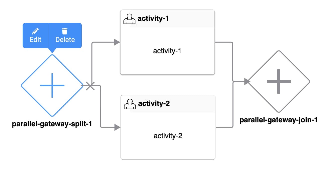
 The Parallel Gateway Split node is one half of the Parallel Gateway set of nodes, along with the Parallel Gateway Join node.
The Parallel Gateway Split node lets you split a single flow of your business process into multiple flows, like the set of Inclusive Gateway nodes. The biggest difference between the Parallel Gateway and Inclusive Gateway nodes is that all split paths run concurrently with the Parallel Gateway.
Situations when you might use the Parallel Gateway set of nodes include:
Executing two or more automated tasks simultaneously, before the end-user progresses to the next task in the workflow.
Allowing multiple team members to work on different tasks in a workflow at the same time.
Executing automated tasks at the same time as end-user tasks.
When you use a Parallel Gateway Split node in your workflow, you must also use a Parallel Gateway Join node. The Parallel Gateway Join node has two jobs:
Pausing the workflow until all parallel tasks that split from the Parallel Gateway Split node are complete.
Merging each state of the submission before it progresses through the rest of the workflow.
To learn more about the Parallel Gateway Join node, view our Parallel Gateway Join Node article.
It's important that all paths split from a given Parallel Gateway Split node reconnect at the same Parallel Gateway Join node. For example, you cannot connect a Handoff or End node to a task or path that splits from a Parallel Gateway Split node. You also cannot connect paths split from the same Parallel Gateway Split node to several Parallel Gateway Join nodes. These rules ensure your workflow cannot reach an endpoint while multiple states of the same submission exist.
Parallel Gateway Split Node Settings
Let's explore the node's Settings Menu. This menu displays as a blue menu bar, either above or below the node, when you select the node itself. This node has these Settings Menu options:
Setting | Description |
|---|---|
Edit | Opens the Edit Parallel Gateway Split window. From there, you can configure settings relating to the Parallel Gateway Split node. |
Delete | Removes the node from the workflow. |
Edit Parallel Gateway Split Window Description
Clicking the Edit button displays the Edit Parallel Gateway Split window.
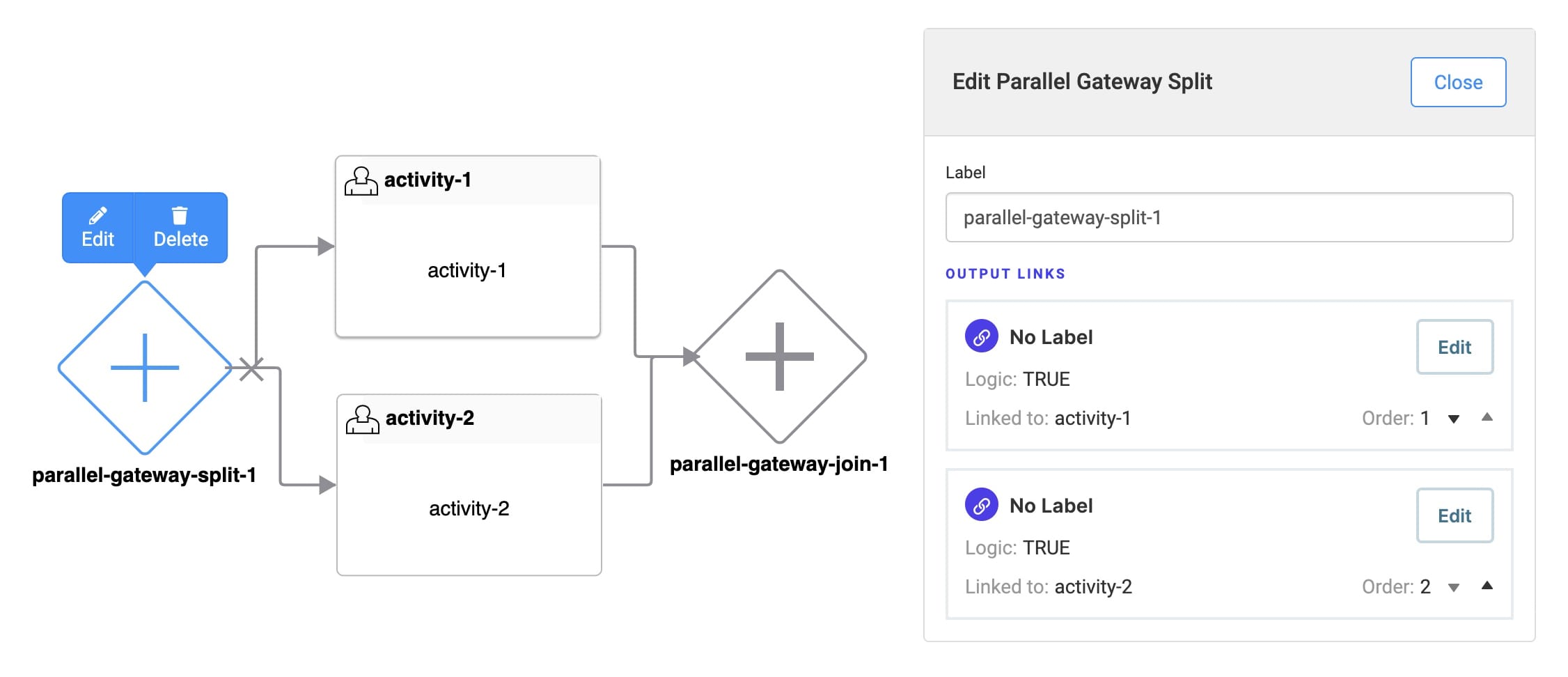
The following settings are available in the Edit Parallel Gateway Split window:
Setting | Description |
|---|---|
Label | The name applied to the node. By default, the Label displays as Labels should be user-friendly and well-associated with the role of the node. |
Output Links | Lists all Parallel Gateway Split Links that split from the Parallel Gateway Split node. Each listed output link shows the link's name, the name of the linked node, and the link's order. Clicking Edit in a listed output link opens the link's Edit Parallel Gateway Link window. |
Link Order | Upon linking other nodes to your Parallel Gateway Split node, the Output Links section populates. By default, links display in the order they were added. You can also manually reorder links using the Order selector. Click the up and down arrow icons to change a link's order. Link ordering helps determine which task your end-user encounters when the workflow progresses through the Parallel Gateway Split node. This is useful when an end-user could potentially access multiple parallel processes. By default, the end-user progresses along the
|
Close Button | Closes the Edit Parallel Gateway Split window. |
Parallel Gateway Split Links
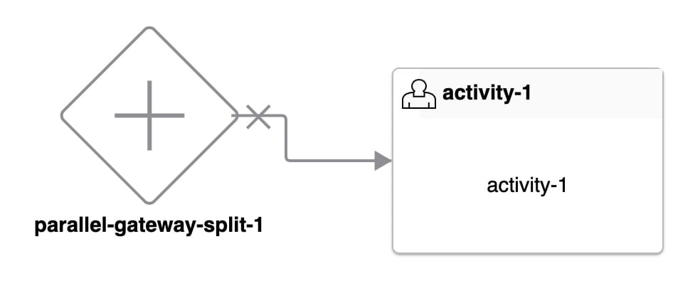 Your Parallel Gateway Split node splits the workflow submission's path. When you connect a Parallel Gateway Split node's output port to another node, the connector becomes a Parallel Gateway Split link. Parallel Gateway Split links look like a directional arrow with a link indicator.
You'll notice that the Parallel Gateway Split link has an X icon along the link. This icon represents the navigation restrictions related to a parallel process. When your end-user proceeds down a Parallel Gateway Split link, they're entering a parallel process. End-users cannot exit that parallel process or enter a new parallel process using the Previous button or Direct Navigation. That way, you can maintain the integrity of the workflow submission while multiple states exist.
Output links from a Parallel Gateway Join node also have an X icon. Parallel Gateway Join links have similar navigation restrictions. After all parallel processes are complete, end-users cannot navigate back to a task that was part of a parallel process.
A Parallel Gateway Split node should connect to at least two nodes before merging at a Parallel Gateway Join node. Doing so creates at least two concurrent workflow paths. Using the Parallel Gateway Split node, the workflow progresses along both paths simultaneously.
Error Handling
When a workflow reaches a Parallel Gateway Split node, all links proceed concurrently. But what happens when one or more link paths encounter an error in between the Parallel Gateway Split and Join nodes? Let's explore some error handling scenarios and see how the workflow behaves.
Error Handling With Only Automated Tasks
You might want to use the Parallel Gateway nodes to run multiple automated tasks in parallel, with no end-user tasks involved. If one or more automated tasks fail, the workflow returns to its state before the split occurred. The end-user stays on the task before the Parallel Gateway Split node.
Error Handling With Automated Tasks Before User Tasks
What happens if you have automated tasks followed by end-user tasks after your Parallel Gateway Split node? If one or more automated tasks fail, the workflow returns to its state before the split occurred. Doing so prevents end-user tasks in one swimlane from completing while another swimlane is experiencing an error.
Parallel Gateway Split Link Settings Menu
Selecting a Parallel Gateway Split link opens a Settings Menu. This menu displays as a blue menu bar, above the link indicator. The menu has the following options:
Setting | Description |
|---|---|
Edit | Opens the Edit Parallel Gateway Split Link window. From there, you can configure settings relating to the Parallel Gateway Split link. |
Delete | Removes the link from the workflow. |
Edit Parallel Gateway Split Link Window Description
Clicking the Edit button displays the Edit Parallel Gateway Split Link window.
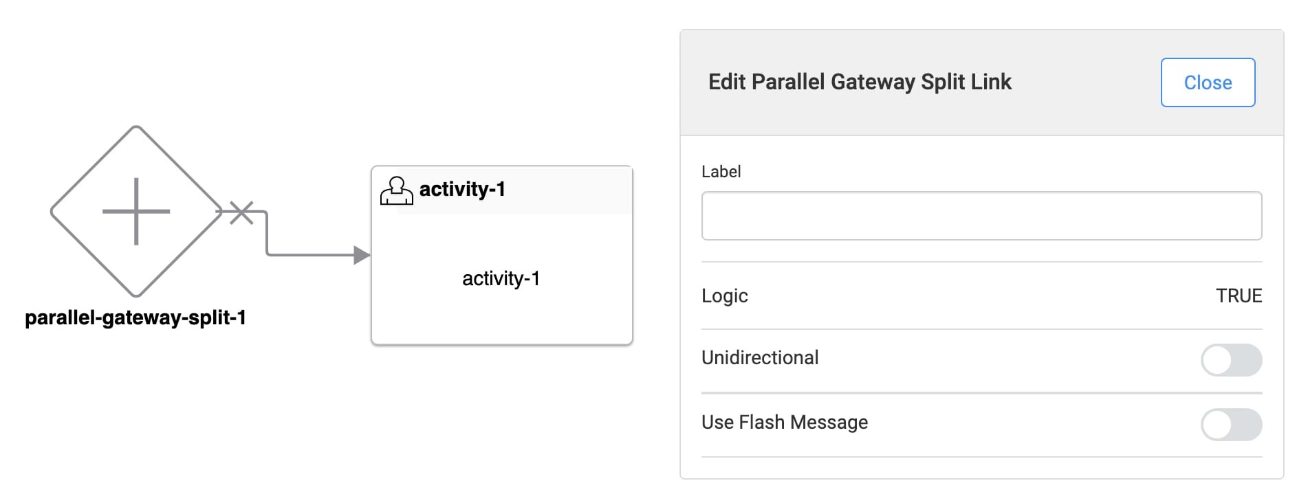
The following settings are available in the Edit Parallel Gateway Split Link window:
Setting | Description |
|---|---|
Label | The name applied to the link. This label is optional and displays below the link once set. Labels should be user-friendly and well-associated with the role of the node. |
Logic | Set to true (logic match). Meaning, all links proceed concurrently. |
Unidirectional | Sets the link one-way. End-users cannot navigate back through a unidirectional link. The link has a double arrowhead when Unidirectional is set to The link has a single arrowhead when Unidirectional is set to By default, the Unidirectional is set to |
Use Flash Message | When set to By default, Use Flash Message is set to |
Flash Message | This setting is visible when Use Flash Message is set to Enter a custom flash message to show in the alert. |
Make Flash Message Dismissible | This setting is visible when Use Flash Message is set to When set to
|
Message Status | This setting is visible when Use Flash Message is set to Select a message status for your flash message. The message status affects the styling of your flash message. The drop-down options are:
|
Adding a Parallel Gateway Split Node
Let's set up a workflow that includes a Parallel Gateway Split node and an accompanying Parallel Gateway Join node. The scenario for this workflow is as follows:
End-users are all involved in helping review and approve changes to a life insurance policy application. The workflow has three different swimlanes with three different roles:
Underwriter
Broker
Automated
The Broker begins the workflow. The first task is to update a life insurance policy application on behalf of a client. After submitting the changes, two required tasks always occur:
The Underwriter assesses that there are previous insurance records for the client, and notes the client's income range.
A Script-type task in the Automated swimlane runs a credit score check.
After all roles complete the required tasks, the Broker reviews the policy application results.
Here's what the workflow looks like in the Workflow Builder:
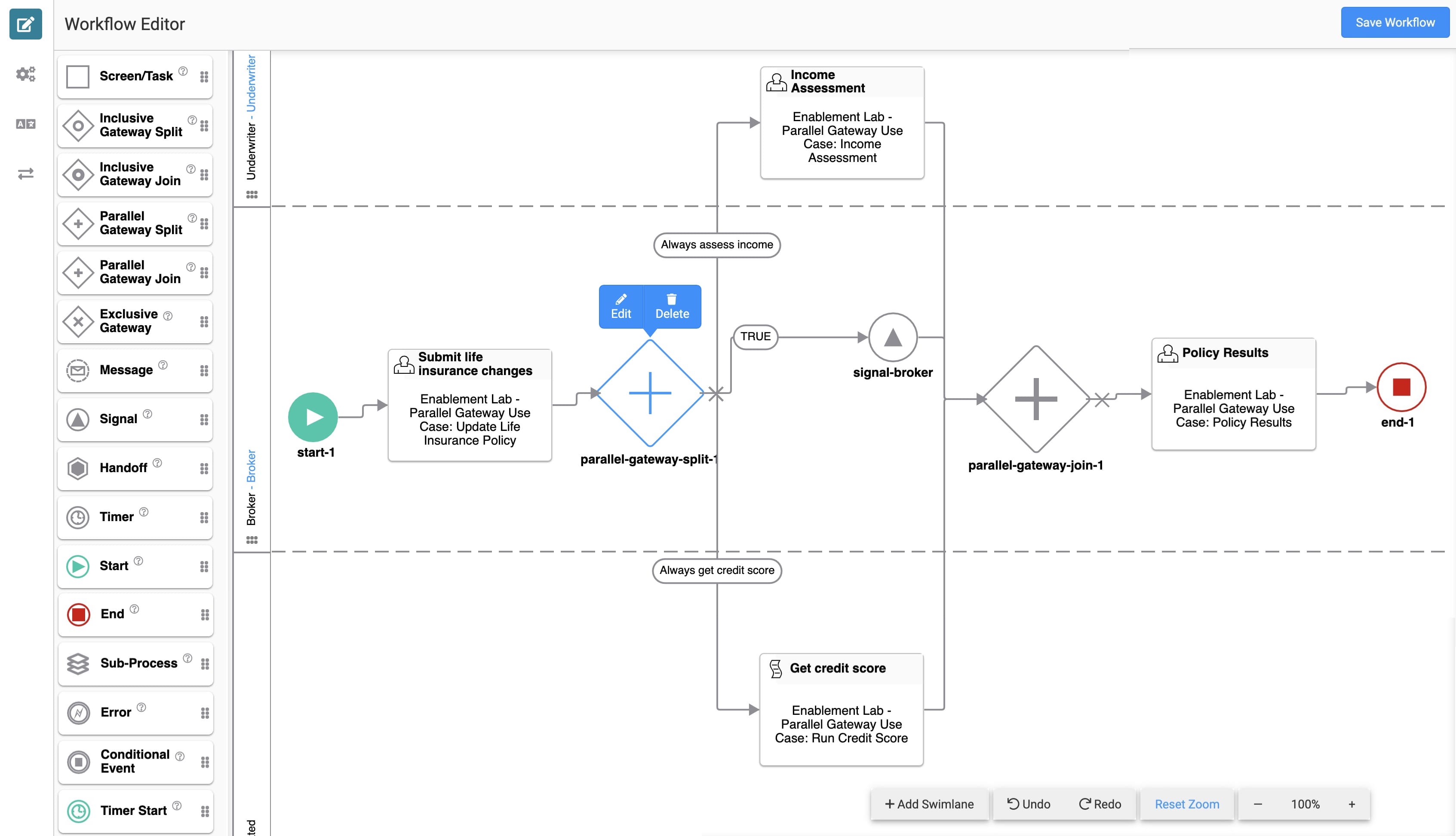
As you can see, the tasks assigned to the Underwriter and Automated roles take place after the Parallel Gateway Split node. Meaning, the Underwriter and Automated swimlane tasks happen in parallel. Once complete, the workflow merges at the Parallel Gateway Join node.
Configure the First Task Node
The Broker uses the first Task node to input some information on behalf of the client.
You can connect this Task node to the following prebuilt module: Enablement Lab - Parallel Gateway Use Case: Update Life Insurance Policy. You can find the module in the Training Environment here: https://training.unqork.io/#/form/613799855a127b4a5566f1d7/edit.
In the Workflow Builder, drag and drop a Task node into the Broker swimlane.
Click Edit.
In the Label field, enter
Update life insurance policy.In the Path field, enter
updatelifeinsurancepolicy.From the Add a Module drop-down, select Enablement Lab - Parallel Gateway Use Case: Update Life Insurance Policy.
Click X (Close).
Connect the input port (left) of the
Submit life insurance changesTask node to the output port (right) of the Start node.
Configure the Parallel Gateway Split Node
Next, you'll add the Parallel Gateway Split node. You’ll set up the rest of the configuration in a later step.
Drag and drop a Parallel Gateway Split node into the Broker swimlane.
Configure the Signal Node
This Signal node lets the Broker know they've completed their tasks. Before the Broker can proceed, the tasks in the Underwriter and Automated swimlanes must be complete. So, you'll set a custom message that notifies the Broker.
Drag and drop a Signal node into the Broker swimlane.
Click Edit.
In the Label field, enter
signal-broker.Set Use Template to
.png) (ON).
(ON).In the Template field, enter
Please wait for all other parties to complete their review of the application.Click X (Close).
Configure the First Parallel Gateway Split Link
Next, let's connect the Parallel Gateway Split node to the Signal node, so the workflow proceeds along this path.
Connect the input port (left) of the
signal-brokerSignal node to the output port (right) of the Parallel Gateway Split node.Click Edit.
In the Label field, enter
TRUE.Click X (Close).
Configure the Second Task Node
You can connect this Task node to the following prebuilt module: Enablement Lab - Parallel Gateway Use Case: Income Assessment. You can find the module in the Training Environment here: https://training.unqork.io/#/form/613799bed812b1475f8d0ee8/edit.
Drag and drop a Task node into the Underwriter swimlane.
Click Edit.
In the Label field, enter
Income Assessment.In the Path field, enter
incomeassessment.From the Add a Module drop-down, select Enablement Lab - Parallel Gateway Use Case: Income Assessment.
Click X (Close).
Configure the Second Parallel Gateway Split Link
Next, let's link the Income Assessment Task node so the application includes an income assessment.
Connect the input port (left) of the
Income AssessmentTask node to the output port (right) of the Parallel Gateway Split node.Click Edit.
In the Label field, enter
Always assess income.Click X (Close).
Configure the Third Task Node
You can connect this Task node to the following prebuilt module: Enablement Lab - Parallel Gateway Use Case: Run Credit Score. You can find the module in the Training Environment here: https://training.unqork.io/#/form/61379a2187604546a8310834/edit.
Drag and drop a Task node into the Automated swimlane.
Click Edit.
In the Label field, enter
Get credit score.In the Path field, enter
getcreditscore.From the Add a Module drop-down, select Enablement Lab - Parallel Gateway Use Case: Run Credit Score.
Click X (Close).
Configure the Third Parallel Gateway Split Link
The last link ensures the application process always runs a credit score check.
Connect the input port (left) of the
Get Credit ScoreTask node to the output port (right) of the Parallel Gateway Split node.Click Edit.
In the Label field, enter
Always get credit score.Click X (Close).
Configure the Parallel Gateway Join Node
Drag and drop a Parallel Gateway Join node into the Broker swimlane.
Connect the output port (right) of the Signal node to the input port (left) of the Parallel Gateway Join node.
Connect the output port (right) of the
Income AssessmentTask node to the input port (left) of the Parallel Gateway Join node.Connect the output port (right) of the
Run Credit ScoreTask node to the input port (left) of the Parallel Gateway Join node.
Configure the Fourth Task Node
You can connect this Task node to the following prebuilt module: Enablement Lab - Parallel Gateway Use Case: Policy Results. You can find the module in the Training Environment here: https://training.unqork.io/#/form/61379a472801e5489ab26a95/edit.
Drag and drop a Task node into the Broker swimlane.
Click Edit.
In the Label field, enter
Policy Results.In the Path field, enter
policyresults.From the Add a Module drop-down, select Enablement Lab - Parallel Gateway Use Case: Policy Results.
Click X (Close).
Connect the input port (left) of the
Policy ResultsTask node to the output port (right) of the Parallel Gateway Join node.
Configure the End Node
Drag and drop an End node into the Broker swimlane.
Connect the output port (right) of the
Policy ResultsTask node to the input port (left) of the End node.Click Save….
Click Save.
Preview your workflow in Express View to view its functionality.
Because this workflow contains several roles with concurrent tasks, you'll need to use the Preview As drop-down to change your preview role as you move through the workflow.