Workflow Links are a tool for defining flow in your workflows. But not all links are the same. Some represent direct flow, while others include logic to determine the flow.
Links are not available from the nodes list on the left. To create links, you must connect nodes using their output and input ports. The type of link differs depending on the nodes you're connecting.
Workflow offers the following link types:
Standard links
Conditional links
Exclusive Gateway links (including Default links)
While all links represent movement through your workflow, you'll use them differently.
Links
You create links when you connect most nodes. Exceptions to these connections include connecting the output ports of the Conditional Event and Exclusive Gateway nodes. A standard link represents movement through your workflow. Conditions, decisions, and logic do not influence these links.
Let's say your end-users navigate from one screen to another in your application. You create Task nodes for activity-1 and activity-2. Then, you drag a connector from the output port of the activity-1 Task node to the input port of the activity-2 Task node. Like other workflows, you'll end and end yours with a Start and End node connected to your Task nodes.
As you can see below, your links look like directional arrows.

Now, let's explore the types of links you can create in Workflows.
Conditional Event Links
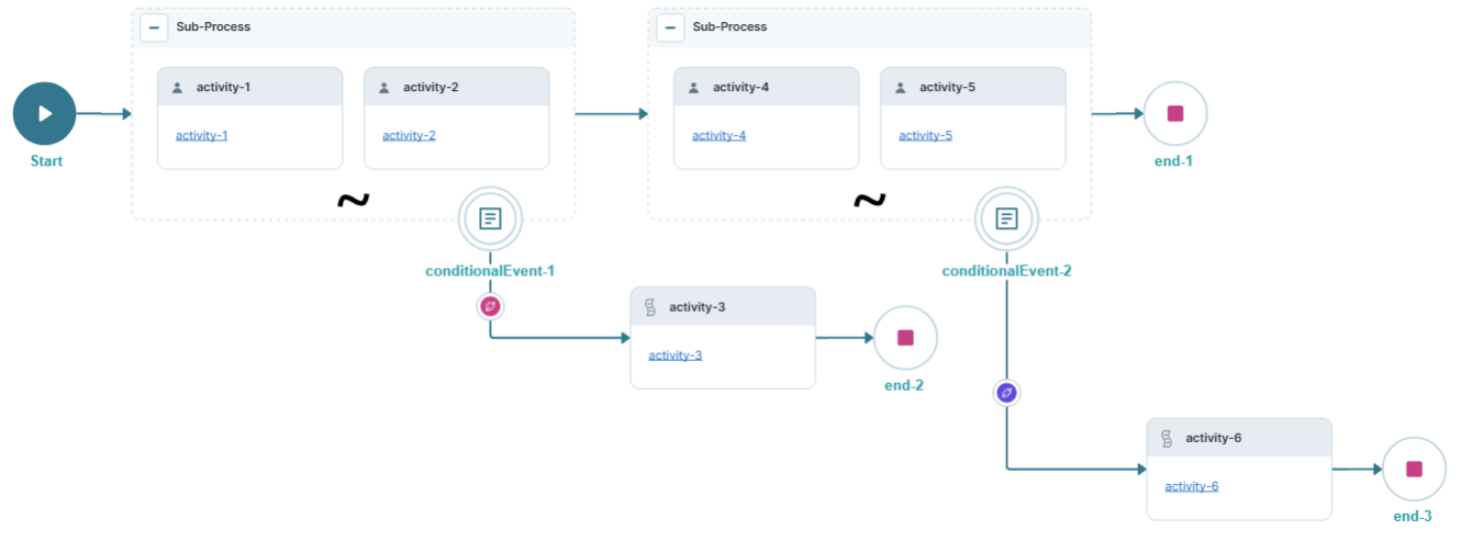
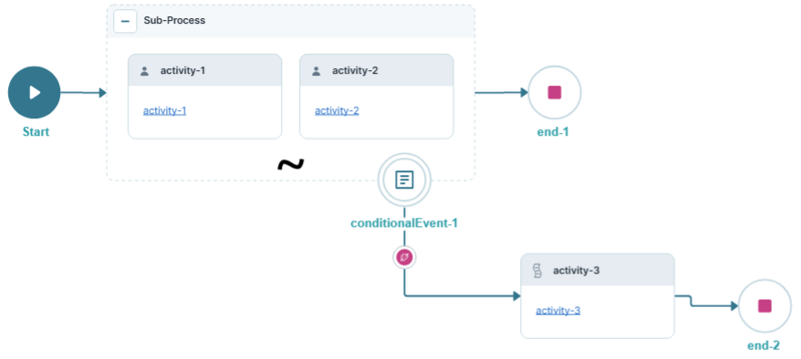
You'll create Conditional Event links when you combine Sub-Process and Conditional Event nodes. These links deviate from your workflow's path based on a specific event and logic statement. Your workflow moves through a Conditional Event link when the logic evaluates as true.
For example, you could have a workflow for approving an application based on a credit score. You might want a different path for end-users with a credit score below 700. From the output port of your Conditional Event node, you'd create one Conditional Event link. You'll use that link's Logic field to trigger an alternate path for scores below 700.
Conditional Event links look like a directional arrow with one of the following link indicators:
Red: The logic is not defined.
Blue: The logic is defined.
Exclusive Gateway Links
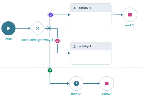
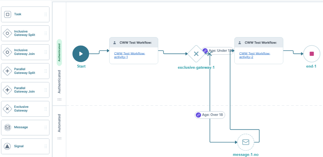
You'll create Exclusive Gateway links when you connect an Exclusive Gateway node's output port to another node's input port. Exclusive Gateway links represent a decision in your workflow, based on a simple logic statement. Your workflow flows through an Exclusive Gateway link when the logic evaluates as true.
For example, you might have different paths for an end-user who answers the following question: “Are you under 18 years old?”. From the output port of your Exclusive Gateway node, you’ll create one Exclusive Gateway link for Yes and another for No.
If you do not make your question required, you can set the link to Default. A Default Exclusive Gateway link determines what happens when none of your Exclusive Gateway links are true. In this case, the end-user leaves the question unanswered.
Default Links
So far, you've learned that all links join nodes. You've also explored how Exclusive Gateway links are unique. There's one more twist to Exclusive Gateway links, called Default links.
Remember, your Exclusive Gateway evaluates decisions as true or false. What happens if none of the paths are true? Which path does your workflow follow? The Default path is where you choose what occurs if none of the paths are true. Without setting a Default path, your end-user could experience a looping workflow. Or the workflow stops without reaching the end. Creating a Default link lets you provide at least one guaranteed path.
After creating an Exclusive Gateway link, you'll edit its settings to make it a Default link. For an Exclusive Gateway link to be a Default link, you must select the Default checkbox in the Settings drawer. You can identify the Default link by its green indicator.
Link Settings Menu Description
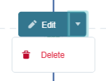
Click on the link to display the Settings menu. Links have the following settings:
Setting | Description |
|---|---|
Edit | Takes you to the Edit Link window, where you can configure related settings. |
Delete | Removes the link from the workflow. |
Edit Link Window Description
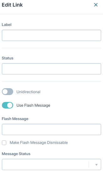
Clicking the Edit button displays the Edit Link window.
Setting | Description |
|---|---|
Label | The name applied to the link. This label is optional and displays below the link once set. Labels should be user-friendly and well-associated with the role of the node. |
Status | You can enter a text value here. Other components can query the Status value of a link. When the workflow passes the link, the Status value populates with the Status field text. |
Unidirectional | Sets the link one-way. End-users can't navigate back through a unidirectional link. The link has a double arrowhead when the Unidirectional setting is set to The link has a single arrowhead when the Unidirectional setting is set to By default, the Unidirectional setting is set to |
Use Flash Message | When set to By default, the Use Flash Message setting is set to |
Flash Message | This setting displays when the Use Flash Message setting is set to Enter a custom flash message for the alert. |
Make Flash Message Dismissable | This setting displays when the Use Flash Message setting is set to When set to
|
Message Status | This setting displays when the Use Flash Message setting is set to Select a message status for your flash message. The message status affects the styling of your flash message. The drop-down options are:
|
Adding a Link
As an example, let’s create a link. These instructions assume that you have a module and a workflow already set up. Your workflow must contain a Start and Task node.
Connect the output port (right) of the Start node to the input port (left) of the Task node.

Click Save….
Click Save.
Changing a Link’s Settings
After you add a link, you can return to its settings and update them.
Click on a link to select it.
Click Edit.
Using the Edit Link window, make changes to the link’s settings as needed.
Click X (Close).
Click Save….
Click Save.
Deleting a Link
Now, let's look at how to remove a link from your workflow. Please note that deleting a link may leave you with an unconnected node.
Click on a link to select it.
Click Delete.
Click Save….
Click Save.
Conditional Event Link
Let’s focus on some details specific to Conditional Event links. The Conditional Event node splits the end-user journey depending on a simple logic calculation. Connecting a Conditional Event node to another node creates the Conditional Event link. The Conditional Event link is where you add that logic. Like nodes, Conditional Event links have a Settings menu where you can add your logic.
Each Conditional Event node is allowed a single Conditional Event link. A Conditional Event link creates an alternate path based on a simple logic statement.
The logic statement can be:
A part of a text string.
A number or range of numbers.
For example, you could check if a numerical variable is less than 500 or if a text variable matches approved. When a workflow reaches a Conditional Event node, it checks the logic in the link. It evaluates whether the statement is true (match) or false (no match). A true logic statement follows your Conditional Event link to your next node.
Conditional Link Settings Menu Description
Click on the Conditional Event link to display the Settings menu. The Conditional link has the following settings:
Setting | Description |
|---|---|
Edit | Opens the Edit Conditional Event link window, where you can configure related settings. |
Delete | Removes the Edit Conditional Event link from the workflow. |
Edit Conditional Event Edit Link Window Description
Clicking the Edit button displays the Edit Conditional Event Link window.
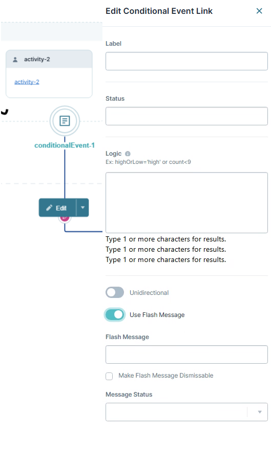
Here's a breakdown of the available settings:
Setting | Description |
|---|---|
Label | The name applied to the link. This label is optional and displays below the link once set. Labels should be user-friendly and well-associated with the role of the node. |
Status | You can enter a text value here. Other components can query the Status value of a link. When the workflow passes the link, the Status value populates with the Status field text. |
Logic | Sets the logic for the Conditional Event link. The expression typically consists of a Property ID, operator, and criteria (value) for matching. For example:
The Logic field also supports Excel formulas. For example:
The Property ID should reference a field accessible to your workflow. For example, a field is present in the workflow submission. The Logic field autopopulates Property ID values as you enter text.
Logic expressions support the following operators: When entering the criteria (value) the formula matches against, you can use a string, integer, or Boolean value. You must wrap strings in single ( |
Unidirectional | Sets the link one-way. End-users can't navigate back through a unidirectional link. The link has a double arrowhead when the Unidirectional setting is set to The link has a single arrowhead when the Unidirectional setting is set to By default, the Unidirectional setting is set to |
Use Flash Message | When set to ON, you can create a flash message for this link. Flash Messages are alerts that display at the top of the workflow in Express View. They show when an end-user navigates past a link that has a Flash Message enabled. By default, the Use Flash Message setting is set to |
Flash Message | This setting displays when the Use Flash Message setting is Enter a custom flash message for the alert. |
Make Flash Message Dismissable | This setting displays when the Use Flash Message setting is set to When set to
|
Message Status | This setting displays when the Use Flash Message setting is set to Select a message status for your flash message. The message status affects the styling of your flash message. The drop-down options are:
|
Adding a Conditional Event Link
As an example, let’s create a Conditional Event link. These instructions assume that you have a workflow already set up. Your workflow must contain the following nodes in the Authenticated swimlane:
Connect the output port (right) of the Conditional Event Node to the input port (left) of a Task Node.
Click Save….
Click Save.
You can only have a single Conditional Event link per Conditional Event node.
Exclusive Gateway Link
Let’s focus on some details specific to Conditional Event links. The Exclusive Gateway node splits an end-user's journey depending on simple logic. When you connect the Exclusive Gateway node's output port to another node, the connector becomes an Exclusive Gateway link. Like nodes, Exclusive Gateway links have a settings menu where you can add your logic.
Your Exclusive Gateway nodes need at least two Exclusive Gateway links from the output port to other nodes in your workflow. Each Exclusive Gateway link you create is a possible decision with a simple logic statement. Your Exclusive Gateway link determines if a statement is true (match) or false (no match). The true logic statements navigate your tasks through your workflow.
The logic statement can be:
A part of a text string.
A number or range of numbers.
For example, you could check if a numerical variable is less than 500 or if a text variable matches approved. When a workflow reaches an Exclusive Gateway node, it checks the logic for all connected Exclusive Gateway links. If a logic statement evaluates as true, the workflow follows that Exclusive Gateway link to the next node. If the logic evaluates as false, and there's a Default Exclusive Gateway link, the workflow proceeds to the default path.
Exclusive Gateway Link Settings Menu Description
Click on the Exclusive Gateway link to display the Settings Menu. The Exclusive Gateway link has the following settings:
Setting | Description |
|---|---|
Edit | Takes you to the Edit Exclusive Gateway Link window, where you can configure related settings. |
Delete | Removes the Exclusive Gateway link from the workflow. |
Edit Exclusive Gateway Link Window Description
Clicking the Edit button displays the Edit Exclusive Gateway Link window.
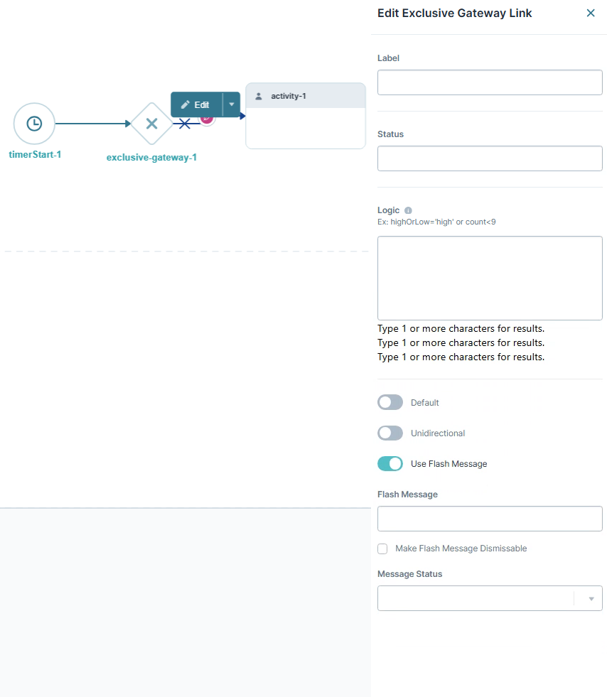
You can also view each Exclusive Gateway link from its connected Exclusive Gateway node.
Here's a breakdown of the available settings:
Setting | Description |
|---|---|
Label | The name applied to the link. This label is optional and displays below the link once set. Labels should be user-friendly and well-associated with the role of the node. |
Status | You can enter a text value here. Other components can query the Status value of a link. When the workflow passes the link, the Status value populates with the Status field text. |
Logic | Sets the logic for the Exclusive Gateway link. The expression typically consists of a Property ID, operator, and criteria (value) for matching. For example:
The Logic field also supports Excel formulas. For example:
The Property ID should reference a field accessible to your workflow. For example, a field displays in the workflow submission. The Logic field autopopulates Property ID values as you enter text.
Logic expressions support the following operators: When entering the criteria (value) the formula matches against, you can use a string, integer, or Boolean value. You must wrap strings in single ( You can also reference global variables in the Logic field. To reference global variables, use the vars syntax with your variable name. For example, |
Default | This setting makes this link the Default link. If no other links evaluate as true, the workflow follows the Default link. You may only have a single Default link per Exclusive Gateway Node. When this setting is set to The Default setting is set to |
Unidirectional | Sets the link one-way. End-users can't navigate back through a unidirectional link. The link has a double arrowhead when the Unidirectional setting is set to The link has a single arrowhead when the Unidirectional setting is set to By default, the Unidirectional setting is set to |
Use Flash Message | When set to ON, you can create a flash message for this link. Flash Messages are alerts that display at the top of the workflow in Express View. They show when an end-user navigates past a link that has a Flash Message enabled. By default, the Use Flash Message setting is set to |
Flash Message | This setting displays when the Use Flash Message setting is set to Enter a custom flash message for the alert. |
Make Flash Message Dismissable | This setting displays when the Use Flash Message setting is set to When set to
|
Message Status | This setting displays when the Use Flash Message setting is set to Select a message status for your flash message. The message status affects the styling of your flash message. The drop-down options are:
|
Adding an Exclusive Gateway Link
As an example, let’s create an Exclusive Gateway link. These instructions assume that you have a module and a workflow already set up. Your workflow must contain an Exclusive Gateway and a Task node.
Connect the output port (right) of the Exclusive Gateway Node to the input port (left) of the Task Node.

Click Save….
Click Save.
Creating a Flash Message
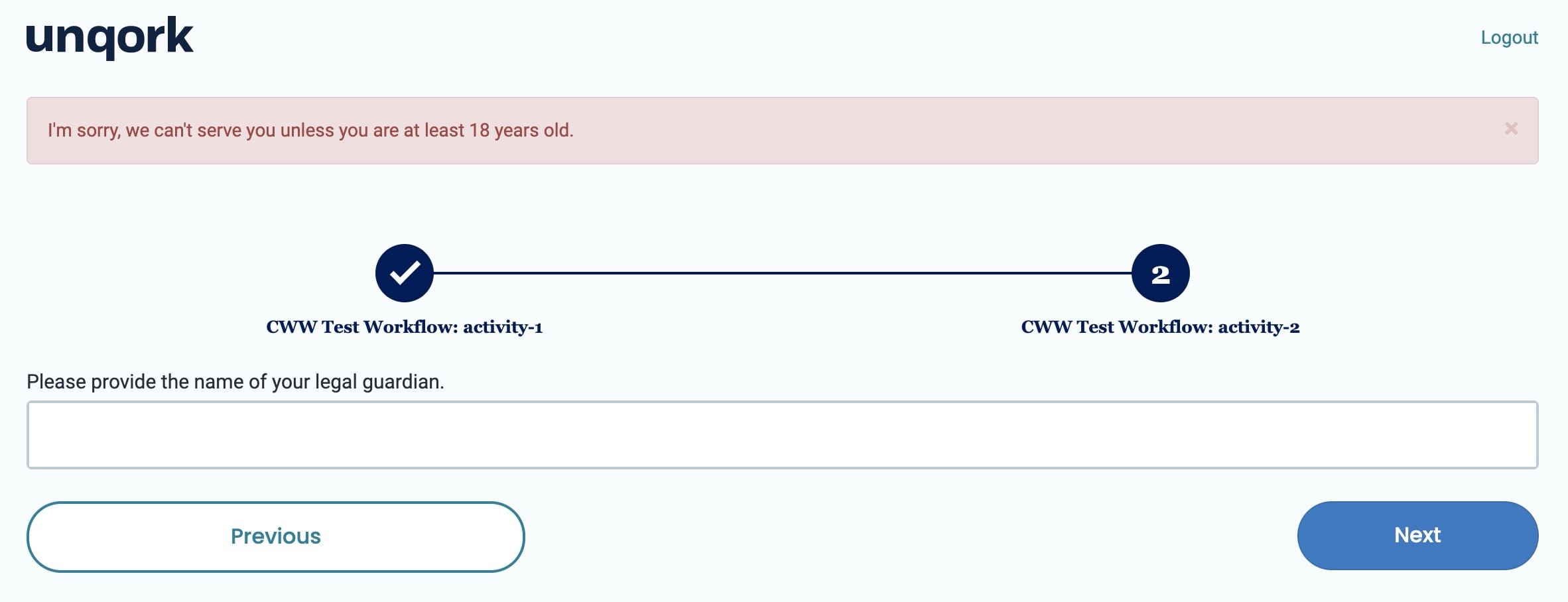
No matter the type of link, you can create a Flash Message. Whenever your end-users navigate past a link with a Flash Message, a message displays at the top of the page. You do not have to use Flash Messages, but they're a great way to communicate with your end-users. You can use these messages to explain why your end-user arrived at a screen. Or, you could thank them for their patronage once they complete an order.
Let’s say you have a module where end-users must be 18 years or older to continue. You provide a Yes/No question that asks, Are you 18 years or older?. If they answer No to the question, a message displays that they cannot continue.
When your end-user clicks Next to advance through the workflow, they’ll see a message. This particular message states: I’m sorry, we can’t serve you unless you're at least 18 years old.
